4 We have not considered Current Diversion and multiple path. Design Calculation are based on IEEE80-2000.

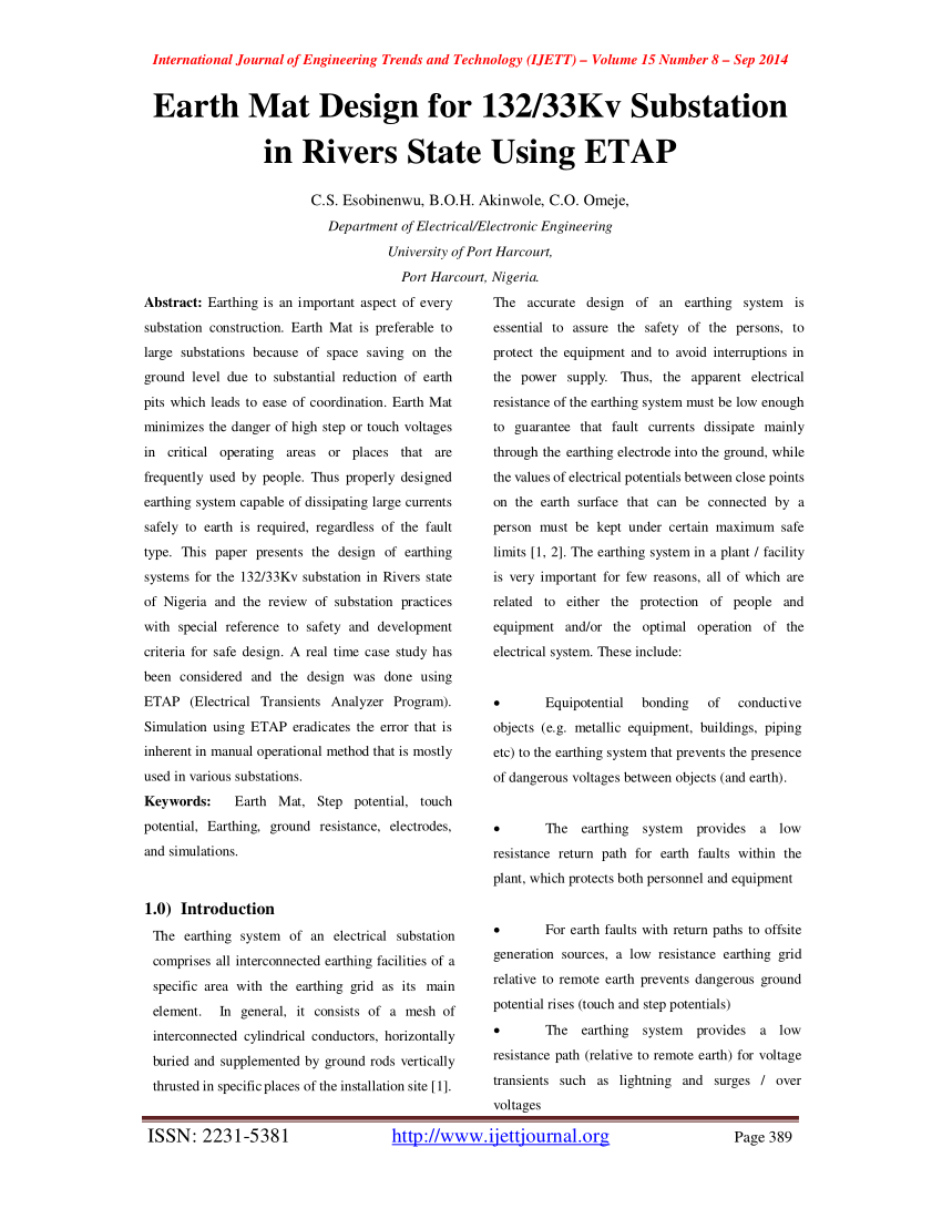
Pdf Earth Mat Design For 132 33kv Substation In Rivers State Using Etap
Calculate the resistance to earth for the configuration.
. 1987 Page 19 clause 921 para 1 Substitute the following for the existing formulaPage 20 clause 922 para 1 Substitute the following for the existing formula. Page 20 clause 922 para 4 Substitute the following for the existing Pipes may be of cast iron of not less than 100 mm diameter 25 to 3 m long and 13 mm thick. MS excel Spreadsheet to help you find earthing values for substation.
Ohm-m for design calculation. Computation of Surface Voltages touch and step 4. EARTH MAT DESIGN CALCULATION FOR 33 KV SSTN for Ms Sukhbir Agro Energy Ltd Shahjahanpur UP.
In our analysis we have considered an area of 275m x 175m. Total Length of Eartning Mat Conductor DESIGN OF EARTHING MAT Earthing Conductor Standard Dia of Conductor mm Estimated Length of Earthing Mat Conductor No of Earthing Rod EARTHING MAT DESIGN FOR SUB STATION As per ANSIIEEE Std 80-1986 codeEnter Your Details. Magnitude of Fault Current Duration of Fault.
D Ground system design. Earthing system thus design must be easily maintained and future expansion must be taken into account while designing the dimensions of earth mat. Earth Current Ground Potential Rise Touch Step 1.
D Earthing mat geometry Area covered by Earth mat. If we divide the area for earthing required by the area of one earth plate gives the no of Earth pits required. Determination of Soil Resistivities 2.
The functions of grounding systems or earth mat in include. B Soil and surface resistivity at the substation site soil structure and soil Model Property and cross-section of material used for earth mat conductor. Maximum Symmetrical Fault current.
NER earth or obvious earth bar in switch-room 2 Use a four terminal earth tester to test continuity between reference earth and the handles of all switches where the grating is to be installed. For Earth Mat Design for HV SStn. Soil Resistivity Resistivity of Surface Material soil structure and soil model.
This paper presents the design of earthing. As the circuit in which the earth or an equivalent conducting body is utilized to allow current circulation from or to its current source. Choose the configuration of the earth electrode according to the shape of the facility.
Of earthing rods 5. Systems for th e 13233Kv substation in R ivers st ate. Any views or opinions expressed by users are personal to them and do not represent the views or opinions of GlobalSpec.
Overstated substation fault current can potentially result in an uneconomical substation earth mat design. Computation of Ground Potential Rise 3. For this purpose a straightforward design based on graphs is proposed.
Check if the calculated resistance meets the design goal. With special reference to safety and. Download PDF - Earthing Mat Design Calculation Sheet en5k0y7m11no.
Different ground systems have different ground resistivity calculations. Mesh network 2. Duration of fault level is 1secas per technical specification.
This paper is concerned with earthing practices and design for outdoor AC substation for power frequency in the range of 50 Hz. Find the area that the buried earth mat will cover. Safety Assessment Basic Problems.
A You should obtain a reading of between 0005 to 0025 ohms. Number of Earthing Electrode and Earthing Resistance depends on the resistivity of soil and time for fault Current to pass through 1 sec or 3 sec. Grounding Design Variables Soil model variables Seasonal modelling of soil Crushed rock resistivity Fault current design margin Fault clearing time Summary Combined.
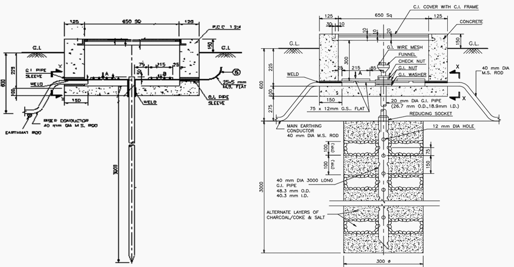
The Average Soil Resistivity measured as. The crossings of the horizontal bars in X and Y directions are welded. It is suggested that the use of a high resistivity surface layer is capable of improving the safety while designing substation-earthing grid in high resistivity.
Design Modelling of Substation Grid 4. The information contained on this site is by users for users and is provided for information purposes only and does not constitute advice. A Magnitude and duration of fault current.
DC substation GIS and. Most affected parameters for design of Earthing. 4 22 Most affected parameters for the Earth Mat design are.
Of Nigeria and the review of substation practices. CALCULATION OF EARTH RESISTANCE. Read about design of substation earthing system here.
SUBSTATION LOA NO CLIENT DOC. Duration of Fault. Ensure safety to personnel in substations against electrical shocks.
Underground Horizontal Earth Mesh MatGrid The mesh is formed by placing mild steel bars placed in X and Y directions in mesh formation in the soil at a depth of about 05 m below the surface of substation floor in the entire substation area except for the foundations. Earth mat design can be done by manual calculations as well as with the help of computer software. Various types of ground systems are shown in Fig.
Is to be considered as 1 Sec. 1 to IS 3043. The grounding system in substation is very important.
An important aspect of substation grounding system design is the calculation of the ground resistance offered by the grounding grid and the values of the mesh and step voltages on the. Cs fault Vin Vout. 1 Identify a suitable reference earth connection in the substations eg.
Earthing Mat Design For Substation. Earth Mat should be design properly by considering the safe limit of Step Potential Touch Potential and Transfer Potential. Though manual calculation is a good software tools ensure a detailed design so that the earth mat is neither under-designed hence safe nor This paper presents the complete design of earth mat for a 3311kV indoor GIS Gas Insulated Switchgear.
EARTH MAT DESIGN CALCULATION REF - IEEE STD-80 2000 PROJECT. I fault I shield I neutral I earth I counterpoise GPR R mat I earth. It will have a considerable impact on grid resistance.
The design of substation earth grids is involved with limiting grid potential rise GPR which is a result of earth fault currents that flow to earth through an earth grid impedance. Graph of grounding resistance vs. Earthing Mat Design Calculation Sheet - Free download as Excel Spreadsheet xls xlsx PDF File pdf Text File txt or read online for free.
So corrosion factor is also specified fault level. Program is designed as per ANSIIEEE 80 Code it calculates step potential of switchyard touch potential of switchyard total length of earthing mat conductor size of earthing mat conductor and total number of earthing rods. Provide the ground connection for connecting the neutrals of stat connected transformer winding to earth.
There is no general rule to.
2

Pdf Design Of Groundmat For 11kv Substation Using Auto Grid Pro
Design Of Earthing System For Extra High Voltage Ac Power Substations Eep
2
2
Pdf Earth Mat Design For 132 33kv Substation In Rivers State Using Etap
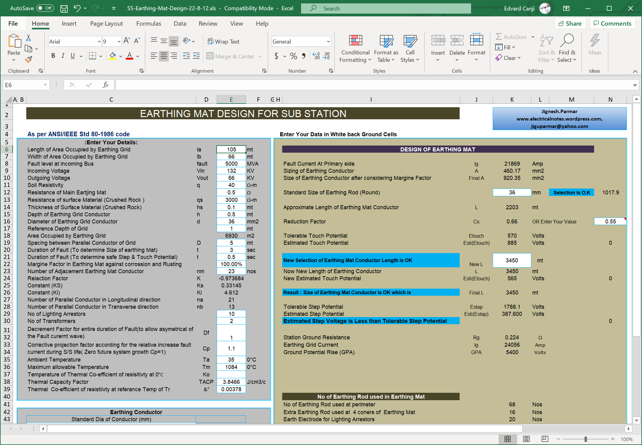
Earthing Mat Design For A Power Substation Ms Excel Spreadsheet Eep

Pdf Etap Model For Earth Mat Design Semantic Scholar
0 comments
Post a Comment